Grove Interface
Introduction
The product is equipped with four standardized modular connection ports (Grove interfaces), which are widely used in the open-source hardware field.
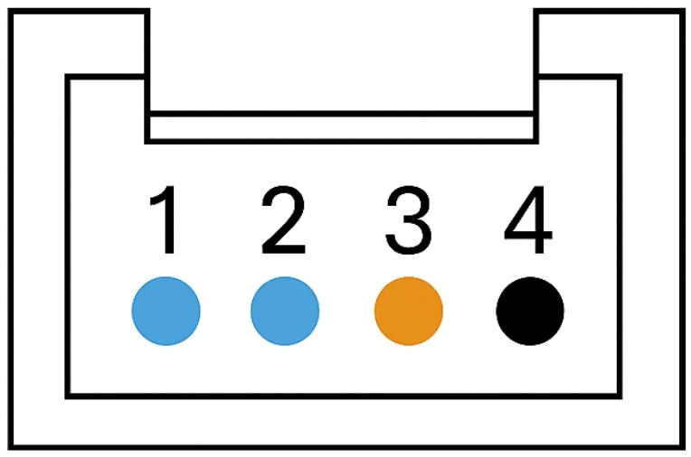
Pin Description
Pin No. |
Description |
|---|---|
1 |
Signal line, e.g., SCL pin of I²C |
2 |
Signal line, e.g., SDA pin of I²C |
3 |
Power positive (VCC) |
4 |
Power ground (GND) |
Instructions for Use
The expansion ports located on the top of the ICRobot support a variety of connection functions.
The Port 1 signal pins are directly connected to the ESP32 chip’s GPIO8 and GPIO40, providing greater flexibility.
This port can function either as an I2C interface or as a standard Grove UART port.
In UART mode, the SCL pin corresponds to RX, and the SDA pin corresponds to TX.
This means that, in addition to I2C-compatible modules, some third-party non-I2C communication protocol sensors can also be connected through this port, depending on the specific device type.
The Ports 2–4 are different: they are expanded via an internal PCA9546 multi-channel I2C expander chip.
Therefore, these ports only support I2C protocol modules and are not compatible with devices using other communication protocols.
Example: Robotic Gripper Object Pickup
Connection Components:
|
|
|
|---|---|---|
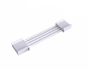
Robotic Gripper ×1 |
ICRobot ×1 |
Grove Cable ×1 |
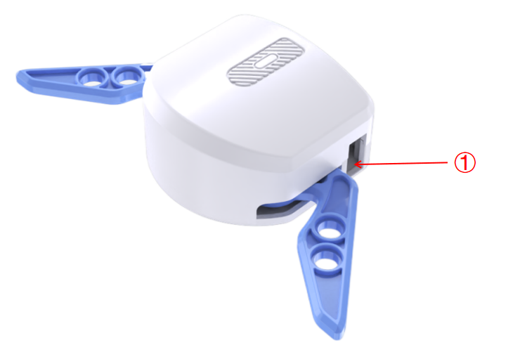
Steps:
Insert one end of the Grove cable into the gripper’s Grove port (as shown in position “①” above).
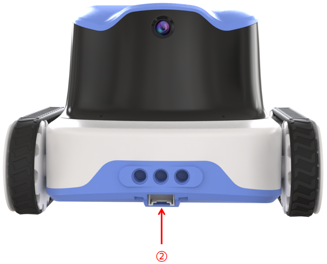
Connect the other end of the Grove cable to any Grove port on the ICRobot — in this example, to Port 2 (as shown in position “②” above).
Programming:
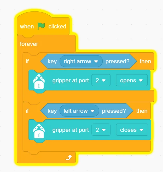
Demonstration